Saturday 6 October 2012

some interview questions


Some Chemical Engineering interview questions - answers compiled here.
  1. Any idea on recombinant protein expression?
  2. Are carbon steel storage tanks appropriate for NaOH solutions?
  3. Are fin tubes necessary for steam heating a liquid?
  4. Cetane no. and sulphur required in diesel fuel for euro-IV
  5. Do you have recombinant protein expression experience? Explain?
  6. Explain the Deacon reaction?
  7. Explain various protein purification techniques?
  8. For a centrifugal pump if the pump is running and we close the discharge valve what is the effect
  9. How are plate heat exchangers used in an ammonia refrigeration system?
  10. how can we derive power factor equation p=vi cos phi? derivation?
  11. how can we measure entropy?
  12. how FOULING effectd the heat transfer rate
  13. How much experience you are having in commercial software for protein design?
  14. how much maximum power can be generated by 320v, 10kg-cm synchronus motor if shaft is roteted mechanically at 50 to 60 rpm?
  15. how to calculat suction head in centrifugal pump?
  16. How to calculate the release flowrates from pressurized gas systems?
  17. How to calculate the sonic velocity of a gas stream?
  18. How to determine the particle size distribution for a given bulk solid?
  19. How to estimate the efficiency of a pump?
  20. Is it possible to compare the resistance to chloride attack of several materials of construction?
  21. Is petroleum a mixture of hydrocarbon?
  22. Name of the fraction at which benzene xylene and toulene is obtained during coal tar distillation
  23. Thyristor related applications
  24. What are some good estimates for heat transfer coefficients for coils in tanks?
  25. What are the affinity laws associated with dynamics pumps?
  26. What are the effects of oils on the properties of Polyolefins?
  27. what are the precautions u are taking while starting HT motors?
  28. What are the steps involved in w.ine making?
  29. What can cause bulk solids to stop flowing from a bin?
  30. What compounds are responsible for the odours that come from wastewater treatment plants?
  31. What does the catalystic converter on an automobile do?
  32. What is a good estimate for the absolute roughness for epoxy lined carbon steel pipe?
  33. What is are the main terms in Unit Operations? and what is its charecteristics?
  34. What is difference between Overall heat transfer coeficient & individual heat transfer coefficient
  35. what is load and what are the types of load?
  36. what is meaning of pid how it is using controlers
  37. What is microstir?
  38. What is Pinch Technology?
  39. what is the apt definitions for apparent power ,active power and reactive power?and explanation about different types of lamps?
  40. what is the differance between Horizental and vertical heat exchanger?
  41. what is the discharge pressure formula, for calculating discharge pressure?
  42. What is the ignition temp. of Alluminium,Coper & Iron.
  43. What is the ignititon temprecher of Diesel,Petrol & Carosion oil.
  44. What is the Import Procurement Cycle ? and what are the customization steps in SAP ?
  45. what is the meaning of flaring
  46. What is the most common cause of solid size segregation in bulk solid systems?
  47. what is the purpose of capacitor? and capacitor load means what? how does it connect?
  48. What is the reason for removing silicon from aluminum?
  49. What is the speed of a rotary drier
  50. What is the symbol of sodium ?
  51. What is the various utilities of the process plant?
  52. What is unit operation?
  53. What regulates, or gives a substance the viscosity it has?
  54. What steps can be taken to avoid stress corrosion cracking (SCC) in steel vessels used for storing anhydrous ammonia?
  55. Which is more effective , a single extraction with a large volume of solvent or several small volume extractions? Explain.
  56. Which reformer efficiencywise best?
  57. Which thing is responsible for making petroleum?
  58. Why is post-weld heat treatment sometimes necessary for welded vessels?
  59. Why is steam added into the cracker in thermal cracking?

Wednesday 19 September 2012

pumps


  • 1. Topic: PUMPS-PIPINGS CENTRIFUGAL PUMPS Pumps are machines that are used to transfer liquid from a location of low elevation to a higher elevation. Classifications: A centrifugal pump consists of a stationary casing and an (1) Dynamic or kinetic impeller connected in rotating shaft. Types of pumps in which energy is continuously added to the fluid to increase its velocity. Centrifugal Jet Turbine pumps (2) Positive displacement Types of pump in which energy is continuously added by application of force to an enclosed volume of fluid and resulting to a direct increase in its pressure. Reciprocating Rotary Diaphragm DISADVANTAGES Poor suction power. Needs multistage to increase discharge pressure. Usually needs priming. Cannot handle very viscous fluid. Cavitation may develop during operation. Check valve is required to avoid back flow. ADVANTAGES Simple and compact. Little vibrations. Easy to maintain. Flow can be controlled from full to non-discharge Adaptability to motor with high rpm. without shutting the pump. PUMP FUNDAMENTALS Water or Hydraulic Power, WP Water or hydraulic power is the energy added by the impeller to the water or fluid as it moves through the pump. WP = Qγ W TDH Where: WP=water or hydraulic power, kW or hp . 1 hp = 0.746 kW ⎡ g ⎤ mW ⎡ go ⎤ . γ W = ρW ⎢ o ⎥ = . ⎢ ⎥ Q= V =pump capacity or volume flow rate, m3/s ⎣ gC ⎦ VW ⎣ gC ⎦ γ W = specific weight of water or fluid For water at standard condition @ 4oC: . ⎡g ⎤ SI units: 9.81 kN/m3 WP = m W ⎢ o ⎥ TDH Eng units: 62.4 lb/ft3 ⎣ gC ⎦ . mW = mass flow rate of water, kg/s or lbm/sec TDH=total dynamic head, m or ft The Total Dynamic Head, TDH Total dynamic head or also known as “pump head” is the total amount of work needed by pump, (usually measured in meters or feet) per specific weight of water flowing through the pump. It is the sum of the elevation head, velocity head, pressure head and head losses. Assumption: Suction Lift Conservation of Energy: [E IN = E OUT ] −PE1 + KE1 + Wf1 + U1 + WP = PE 2 + KE2 + Wf 2 + U2 WP = (PE 2 + PE1 ) + (KE2 − KE1 ) + (Wf 2 − Wf1 ) + (U2 − U1 ) If we assume that the temperature from the suction and discharge of the pump are almost equal, t1 ≈ t 2 , then we can say that the . . change in internal energy is negligible, ΔU ≈ 0 . We can also assume a steady state pumping process for the pump, V 1 ≈ V 2 . DAY 10 Copyright 2010 www.e-reviewonline.com
  • 2. Topic: PUMPS-PIPINGS . WP = mW . go gC 2 gC ( (z 2 + z1 ) + 1 mW v 2 2 − v12 + V W (P2 − P1 ) . ) gC Multiplying both sides of the equations by . . mW go gC WP = (z 2 + z1 ) + ( 1 v 2 − v1 2 2 )+ (P 2 − P1 ) . 2 go . mW go m W ⎡ go ⎤ ⎢ ⎥ . g VW ⎣ C ⎦ TDH = gC WP = (z 2 + z1 ) + ( 1 v 2 − v1 2 2 )+ (P 2 − P1 ) . 2 go . mW go mW ⎡ go ⎤ ⎢ ⎥ . g VW ⎣ C ⎦ Therefore: TDH = (z 2 + z1 ) + ( 2 1 v 2 − v1 2 ) + (P 2 − P1 ) 2 go γW If we take into considerations all the head losses, hL due to fluid friction in the pipes, elbows, valves and fittings we will have: TDH = (z 2 + z1 ) + ( 2 1 v 2 − v1 2 ) + (P 2 − P1 ) + hL 2 go γW TDH = (total static head) + (velocity head) + (pressure head) + (friction head) TDH = hS + hV + hP + hL Total Static Head, hs Static head is the vertical distance where the pump must lift the water. It measured from the water level surface to the discharge point. Static Suction Lift Suction lift is present when the water source is below the pump centerline. Static Suction Head Suction lift is present when the water source is above the pump centerline. Velocity Head, hV Velocity head is the energy possessed by the fluid because of its velocity. Velocity head is usually very small that it can be neglected in the calculation. Pressure Head, hP Pressure head is the pressure required for the pump to distribute water properly. A 60 psi water pressure is equivalent to 138.5 feet of water. Friction Head, HL Friction head is the head associated with the decrease in pressure due to friction when the fluid is flowing through the pipes, valves and fittings. Pump Efficiency The pump efficiency is the ratio of the water or hydraulic power output of the pump over the brake power input to the pump. WP ηP = * 100% BP PUMP SPECIFIC SPEED Pump specific speed is a dimensionless parameter Where: Ns = specific speed of the pump, rpm used to describe hydraulic features of centrifugal pumps. It is Q = capacity of the pump, gpm defined as the revolution per minute at which a given 1 gallon = 3.78 Liters geometrically similar impeller of a pump would operate if H = pump head per stage, ft reduced proportionally in size so as to deliver a rated capacity 1 meter = 3.28 feet of 1 gallon per minute against a head of 1-foot. Note: For double suction pumps Q is divided by 2 and for multi-stage pumps, H is divided by the number of stages. N=impeller speed, in revolutions per minute N Q NS = H3 / 4 DAY 10 Copyright 2010 www.e-reviewonline.com
  • 3. Topic: PUMPS-PIPINGS NET POSITIVE SUCTION HEAD, NPSH Net Positive Suction Head, NPSH, is an index where the pump may operate without cavitation. Cavitation Cavitation occurs when the pressure at any point inside the pump drops below the vapor pressure corresponding to the temperature of the liquid. The liquid vaporize and forms vapor bubbles as it enters the inlet of the pump. This vapor bubbles then collapse or implodes at the surface of the impeller creating tremendous physical shock to the edges of the impeller. NPSH Required NPSHr for a particular pump is experimentally determined and provided by the manufacturer and is a function of the pump design. NPSH Available NPSHa is determined by plant designer during the design and proposed installation of the pump and is a function of the system where the pump will operate. To avoid cavitation: NPSHa ≥ NPSHr NET POSITIVE SUCTION HEAD AVAILABLE, NPSHa NPSHa = hP ± hSL − hV − HL Where: hP = absolute pressure head on the surface of the liquid source, in meters. This will be the atmospheric pressure corresponding to its altitude when the liquid surface is open. hSL = the height of the liquid surface from the pump center line, designated as positive when suction head and negative when suction lift, in meters hV = head corresponding to the vapor pressure of the liquid at liquid temperature, can be determined using steam tables, in meters HL = head loss due to friction and turbulence, in meters If NPSHa ≤ NPSHr , there are two possible options available: (1) Decrease the suction lift by changing the plant layout and raising the source on which the pump draws water. (2) Reduce the suction head by using pumps with larger capacity but operating it in partial loads or speeds. PUMP AFFINITY LAWS Pump affinity laws are rules that express the relationship of pump capacity, head and BHP when the speed or impeller diameter is changed. In applying the following equations, we consider that the efficiency is the same for both conditions. Impeller Speed, N, held diameter, D, constant Where: Q = Capacity, in gpm held constant N1 = N2 H = Total head, in feet D1 = D2 BHP = Brake horsepower, in hp Q1 N Q1 D N = Pump speed, rpm Capacity = 1 = 1 Q2 N2 Q2 D2 Subscript 1 refers to initial condition and subscript 2 refers to the new condition. 2 2 H1 ⎛ N1 ⎞ H1 ⎛D ⎞ Head =⎜ ⎟ =⎜ 1 ⎟ H2 ⎜ N2 ⎝ ⎟ ⎠ H2 ⎜D ⎝ 2 ⎟ ⎠ 3 3 BHP1 ⎛N ⎞ BHP1 ⎛D ⎞ BHP =⎜ 1 ⎜N ⎟ ⎟ =⎜ 1 ⎜D ⎟ ⎟ BHP2 ⎝ 2 ⎠ BHP2 ⎝ 2 ⎠ Characteristics of Reciprocating Pumps b. Considering Piston Rod VD = π 2 4 π ( D LN + D2 − d2 LN 4 ) 2. Slip = VD - Q 3. Percent slip Q % slip = 1 − 1. Piston displacement VD a. Neglecting Piston Rod ⎡ D2 ⎤ ⎡ c a (n / 60) 2 ⎤ 4. Volumetric Efficiency, η V From: VD = ⎢π ⎥L⎢ ⎥ ⎣ 4⎦ ⎣ s ⎦ s=2 for pumps and compressors η V = 1 − slip c=1 and a=2 Q ⎛ V1 ⎞ ⎡π ⎤ ηV = = 1+c −c ⎜ ⎟ VD = 2 ⎢ D2LN⎥ VD ⎜V ⎟ ⎝ 2 ⎠ ⎣ 4 ⎦ DAY 10 Copyright 2010 www.e-reviewonline.com
  • 4. Topic: PUMPS-PIPINGS Pump Installation Pumps in Series Pumps in Parallel Pumps in series are done by staging two pumps as Pumps in parallel are the result of installing two shown in Figure. The total dynamic head is increased at a pumps as shown in Figure. The capacity is doubled while given capacity as shown in the performance curve. maintaining the total dynamic head. Pipe Friction Head Pipe is defined as a closed conduit in which fluids flow. Piping systems are very important in transporting liquid or gasses like in oil refineries, air conditioning, water works, and food processing industries. Pressure Losses The total pressure loss in a piping system is composed of major and minor losses. In this section, we will tackle the major and minor frictional losses caused by pipe surface friction, changes in fluid velocity and direction. Major Losses, hf Major losses or also known as pipe friction losses, hf, they are losses along the pipe surface and are assumed to be uniform as long as the size and the type of material of the pipe remain constant. Minor Losses, hL Minor losses, hL, consist of losses due to the following: Contraction of pipe cross section, hc Enlargement of pipe cross section, he Obstructions such as valves, gates and fittings, hg Bends or curves, hb The total losses, HL, in a pipe line are the sum of the major and minor losses; HL = hf + hL HL = hf + (hc + he + hg + hb) Darcy-Weisbach Equation Darcy-Weisbach equation expresses the loss of head Reynolds Number, Re in pipes in terms of the velocity head. Reynolds number is a dimensionless parameter discovered by Osborne Reynolds in 1883, which determines L v2 whether the flow in a closed conduit or a pipeline is laminar or hf = f turbulent. D 2go Dvρ Where: f = resistance coefficient or friction factor Re = Note: If tables are not available, use f = 0.02 μ L = Total pipe length including valves and fittings equivalent length, m Where: D = Inside diameter of the pipe, m D = Inside diameter of the pipe, m v = Liquid velocity, m/s v = Liquid velocity, m/s ρ = Density of the fluid, kg/m3 go = observed gravitational acceleration, m/2 μ = Dynamic viscosity, Pa-s or Poise dyne − s Note: 1 poise = 1 = 0.1 Pa-s m2 If the dynamic viscosity is divided by the density, kinematic viscosity, ν, can be obtained: μ ν = ρ Therefore; Dv Re = ν Where: ν = Kinematic viscosity, m2/s Note: 1 stroke = 1 cm2/sec DAY 10 Copyright 2010 www.e-reviewonline.com
  • 5. Topic: PUMPS-PIPINGS Friction Factor, f, for Turbulent and Laminar Flow If R e ≥ 3000 the flow is turbulent and the friction If R e ≤ 2000 the flow is said to be laminar, and the factor, f, will be dependent on the Reynold’s number and the friction factor, f can be determined using the relationship: relative roughness: 64 f = ⎛ ε⎞ Re f = ∫ ⎜R e , ⎟ ⎝ D⎠ Relative Roughness Relative roughness is the ratio of the pipe inside surface irregularities (absolute roughness), ε , to the pipe diameter, D. ε Re lative Roughness = D Minor Losses Minor losses are determined using the relationship: Where: kL = loss coefficient for contraction, enlargement, gate, valves, fittings and v2 bends. hL = ∑ k L Note: The values of kL (if not given) can be 2go found in published tables Pipes of different diameters connected in series Figure shows a simplified diagram of flow in a series pipeline with different diameters connecting two Total head loss: reservoirs. HL = hf1 + hf2 + hf3 Volume flow rate: Q = Q1 = Q2 = Q3 Pipes connected in parallel Figure shows a simplified diagram of flow in a parallel pipeline connecting two reservoirs. The pipe Total head loss: line 1 from reservoir A divides the flow at C and then HL = hf1 + hf2 + hf4 joins again at D. Pipeline 4 leads to reservoir B. hf2 = hf3 Volume flow rate: Q1 = Q2 + Q3 Q1 = Q4 DAY

Monday 17 September 2012

centrifugal pump basic

Centrifugal Pumps 

Centrifugal: "Moving or directed away from the center (or axis)"

Centrifugal pumps are the most common type of pump used in plumbing systems. This article explores the basic design concepts and functional principals of these pumps.

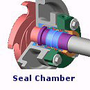
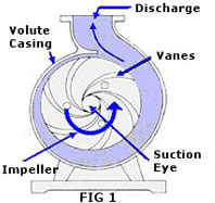
Fig 1 illustrates a cross-section of a typical centrifugal pump.

Fluid enters the inlet port at the center of the rotating impeller, or the suction eye.

As the impeller spins in a counter-clockwise direction, it thrusts the fluid outward radially, causing centrifugal acceleration.

As it does this, it creates a vacuum in its wake, drawing even more fluid into the inlet. 

Centrifugal acceleration creates energy proportional to the speed of the impeller. The faster the impeller rotates, the faster the fluid movement and the stronger its force. This energy is harnessed by introducing resistance.

Remember, a pump does not create pressure; it only provides flow.
Pressure is a measure of the amount of resistance to that flow.


A centrifugal pump has two main components, one moving and one stationary.


The moving component consists of an impeller and a shaft.


The stationary component consists of a casing, cover, and bearings. These are illustrated at the left, in Fig 2.


Moving Components: Impellers & Shafts

Impeller

Impellers are the rotating blades that actually move the fluid. They are connected to the drive shaft that rotates within the pump casing. The impeller is designed to impart a whirling or motion to the liquid in the pump.

Impellers are classified in a number of different ways:

  1. Direction of flow relative to the axis of the shaft.
    - Radial flow
    - Axial flow
    - Mixed flow
  2. Type of suction
    - Single-suction (Liquid inlet on one side)
    - Double-suction (Liquid inlet on both sides)
  3. Mechanical construction (FIG 3)
    - Open: No shrouds or wall to enclose the vanes
    - Closed: Shrouds or sidewall enclosing the vanes
    - Semi-open or vortex type.

    Open and semi-open impellers are less prone to clogging, but require manual adjustment to the volute or back-plate to prevent internal re-circulation.

    Closed impellers require wear rings, which must be replaced periodically, presenting a maintenance problem.

    Vortex impellers are effective for solids and fibrous materials but they are less efficient than other designs.

Stages
The number of impellers determines the number of stages of the pump.
  • SingleStage pump has just one impeller and is better for low head service
  • Two-Stage pumphas two impellers mounted in series for medium head service.
  • Multi-Stage pump has three or more impellers mounted in series for high head service such as in deep well pumps.
Impeller Class (Shape)
Specific Speed is used to classify pump impellers as to their type and proportions.

It is defined as the speed in RPMs (revolutions per minute) at which a similar impeller would have to operate in order to deliver one gallon per minute flow against one-foot head.

The specific speed determines the general shape or class of the impellers.

Radial flow impellers develop head principally through centrifugal force. Radial impellers are generally used in low flow high head designs, while Axial impellers are used in high flow low head designs. Pumps of higher specific speeds develop head partly by centrifugal force and partly by axial force.

Shafts
Shaft Sleeves extend beyond the outer face of the seal gland plate and protect the shafts from erosion, corrosion, and wear. 

Leakage between the shaft and the sleeve is different
from leakage through the mechanical seal

Shaft Couplings compensate for axial growth of the shaft and transmit torque to the impeller. They may be either rigid or flexible.

Rigid couplings are used when there is chance of misalignment. Flexible couplings are more forgiving, and may be either elastomeric (using rubber or polymer parts) or non-elastomeric (using metallic parts). 


Stationary Components: Casing 

Casing
The pump casing creates the first resistance. The liquid decelerates still more in the discharge nozzle, where its velocity is converted to pressure

Casings are generally either volute or circular.

A volute is a curved funnel that increases in size to the discharge port. As its size increases, the volute reduces the speed of the liquid and increases the output pressure.

This helps to balance hydraulic pressure on the shaft; however, running volute-style pumps at slow speeds puts undue stress on the shaft, which in turn increases wear-and-tear on the seals and bearings, as well as on the shaft itself.

Volute casings build a higher head, but circular casings are generally used on higher capacity pumps. Circular casings have stationary diffusion vanes around the impeller that convert velocity energy to pressure energy. Diffusers are typically used in multi-stage pumps.

Casings are either solid or split.

In a solid casings design the entire casing is in one piece. Split casings are made of two or more parts fastened together, split either horizontally (axially split), or vertically (radially split). Wear rings seal the casing from the impeller.

Suction and discharge nozzles are built into the casings. They are typically made in one of the following ways:
  • End suction/Top discharge. The discharge nozzle is perpendicular to the shaft.
  • Top suction /Top discharge. Both nozzles are perpendicular to the shaft. This pump is always a radially split case pump.
  • Side suction / Side discharge. Both nozzles are perpendicular to the shaft. This pump can have either an axially or radially split case type.

The space between the shaft and casing is called the chamber.

If a mechanical seal is used in the pump, the chamber is commonly referred to as a Seal Chamber.

If packing is used to form the seal, the chamber is referred to as a Stuffing Box.

Both the seal chamber and the stuffing box protect the pump against leakage where the shaft passes through the casing. They also maintain proper temperature control.

An adjustable gland helps the packing or the seal fit properly on the shaft sleeve. The throat or throttle bushing forms a close clearance around the sleeve. An internal circulating device (pumping ring) circulates fluid through a cooler or reservoir. 

Bearings
The bearing housing encloses the bearings that keep the shaft in correct alignment with the stationary parts. It also includes an oil reservoir for lubrication, oiler, and cooling jacket.

Auxiliary ComponentsAuxiliary components generally include seal drains, vents, and cooling systems, bearing lubrication, seal chamber or stuffing box cooling, and pump pedestal cooling systems.

Auxiliary piping systems may include tubing, piping, various types of valves and gauges, thermocouples, sight flow indicators, fluid reservoirs, and all related vents and drains.

Pump CapacityCapacity is the flow rate in gallons per minute (GPM) at which liquid is moved or pushed by the pump.

Capacity depends on the pressure, temperature, and viscosity of the liquid being pumped, the size of the pump and the shape of the cavities between the vanes, and on the size and speed of the impeller.

Note: Pressure output of pumps is measured as "feet of head" rather than "pounds per square inch"


Since liquids are essentially incompressible, capacity is directly related with the velocity of flow in the suction pipe. This relationship is as follows:
       Q = 449 x V x A
        Q = Capacity in gallons per minute
        V = Velocity in flow in feet per second
        A = Area of pipe in square ft.

Power and Efficiency
Brake Horsepower (BHP) is the actual horsepower delivered to the pump shaft, defined as follows:

       BHP = Q x Hr x Sp. Gr.
              3960 x Eff.

        Q = Capacity in gallons per minute
        Hr = Total Differential Head in absolute feet
        Sp. Gr. = Specific Gravity of the liquid.
        Eff. = Pump efficiency as a percentage

Water Horsepower (WHP) is the hydraulic horsepower delivered by the pump, defined as follows:

      WHP = Q x Hr x Sp/Gr.

                  3960

        Q = Capacity in gallons per minute
        Hr = Total Differential Head in absolute feet
        Sp. Gr. = Specific Gravity of the liquid

The constant (3960) is the number of foot-pounds in one horsepower (33,000) divided by the weight of one gallon of water (8.33 pounds).

Brake horsepower is always greater than hydraulic horsepower due to the friction in the pump. Pump efficiency is the ratio of these two values.
Pump Efficiency = WHP
BHP

Best Efficiency Point (BEP) is the capacity at maximum impeller size at which the efficiency is highest.

All points above or below BEP have a lower efficiency, and the impeller is subject vibration, heat, and cavitation. This causes premature bearing and mechanical seal failures due to shaft deflection, and heat will cause seizure of close tolerance parts and cavitation.

A high efficiency pump uses less energy ($$$) to operate than a low efficiency pump. If possible, it is best to avoid any pump that has an efficiency of 55% or less. (55% efficiency is the industry standard used to estimate the performance of a pump when the actual efficiency is unknown.)

Pump Curve
A pump curve is a simple graph which shows the performance characteristics of a particular pump.

Pump curves are created by the pump manufacturer based on test results of the various pump models the manufacturer produces.

Remember, there is always an inverse relationship between pressure and flow. Higher pressures mean lower flows. Lower pressures result in higher flows.


Each pump curve typically reflects a single model of pump made by the manufacturer. (A typical pump curve is shown at the right)

The top right of the chart shows the pump speed; in the chart above this is 3500 RPM. Two variables affect the pump performance, horsepower of the motor and the size of the impeller.

The left side of the curve is labeled HEAD - FT. This is the distance the pump is capable of lifting the fluid. The bottom of the curve is labeled US GPM. This is the flow that the pump produces.

The red upper curved lines represent the various impeller sizes. The green straight lines represent the motor horsepower ratings available for this pump. Together they represent the best performance the pump is capable of with a selected motor or impeller size.

If a pump is only available with one motor, it will not have separate horsepower lines. If the pump is available with only one size of impeller, there will be just a single line on the entire pump curve!

Based on the above curve, an output of 125 ft hd at 100 GPM would require a 5 HP motor and a 6 inch diameter impeller. Similarly, an output of 70 ft. hd. at 80 GPM would require a 3 HP motor with a 5 inch diameter impeller.

NPSH FT (shown in the lower right of the graph) is the maximum height that a pump can be above the water. This does not apply to submersible, jet, or turbine pump because the pump is underwater. It also does not apply to booster pumps because water is already being forced into them from the water source.

Pumps can sometimes be ordered with custom impeller sizes. This often does not cost much more than a stock pump, but it will delay the delivery since they are custom built.

boundary layer concept


Viscosity and Boundary Layers


This chapter deals with the effects of viscosity in two dimensions. The sections describe the basic phenomena and some simple theory that may be used to estimate boundary layer properties.

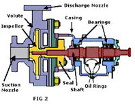
Boundary layers appear on the surface of bodies in viscous flow because the fluid seems to "stick" to the surface (*see note). Right at the surface the flow has zero relative speed and this fluid transfers momentum to adjacent layers through the action of viscosity. Thus a thin layer of fluid with lower velocity than the outer flow develops. The requirement that the flow at the surface has no relative motion is the "no slip condition."

The velocity in the boundary layer slowly increases until it reaches the outer flow velocity, Ue.

The boundary layer thickness, δ, is defined as the distance required for the flow to nearly reach Ue. We might take an arbitrary number (say 99%) to define what we mean by "nearly", but certain other definitions are used most frequently. (see theory section).

The boundary layer concept is attributed primarily to Ludwig Prandtl (1874-1953), a professor at the University of Gottingen. His 1904 paper on the subject formed the basis for future work on skin friction, heat transfer, and separation. He subsequently made fundamental contributions to finite wing theory and compressibility effects. (His name appears about 30 times in these notes.) Theodore von Karman and Max Munk were among his many famous students. R.T. Jones was a student of Max Munk and I have subsequently learned a great deal from R.T. Jones -- which makes readers of these notes great-great grandstudents of Prandtl.
The character of the boundary layer changes as it develops along the surface of the airfoil. Generally starting out as a laminar flow, the boundary layer thickens, undergoes transition to turbulent flow, and then continues to develop along the surface of the body, possibly separating from the surface under certain conditions.


In laminar flow, the fluid moves in smooth layers or lamina. There is relatively little mixing and consequently the velocity gradients are small and shear stresses are low. The thickness of the laminar boundary layer increases with distance from the start of the boundary layer and decreases with Reynolds number.


As the fluid is sheared across the surface of the body, instabilities develop and eventually the flow transitions into turbulent motion.

Turbulent boundary layer flow is characterized by unsteady mixing due to eddies at many scales. The result is higher shear stress at the wall, a "fuller" velocity profile,and a greater boundary layer thickness. The wall shear stress is higher because the velocity gradient near the wall is greater. This is because of the more effective mixing associated with turbulent flow. However, the lower velocity fluid is also transported outward with the result that the distance to the edge of the layer is larger.


Several fundamental effects are produced by viscosity:

Drag: Skin friction drag caused by shear stresses at the surface contribute a majority of the drag of most airplanes.

The pressure distribution is changed by the presence of a boundary layer, even when no significant separation is present. This changes CL and Cm.

Flow separation: Viscosity is responsible for flow separation which causes major changes to the flow patterns and pressures.


To compute these characteristics some basic boundary layer theory is described here with more detailed computational methods for laminar and turbulent boundary layers.


*Actually, the zero slip condition at the surface arises from the roughness of the surface on a molecular scale. Fluid molecules hitting the surface impart a net momentum to the surface and the mean velocity of molecules hitting the surface is about the same as the surface velocity.
Even when the surface is extremely smooth, electrostatic forces exist between the surface and the air molecules, introducing the shear stress at the surface. If this interaction could be reduced, a reduction in skin friction would result, but no one has found a way to do this.